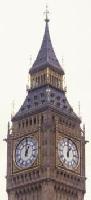
At the time of its construction, 1854, the movement of the Great Clock was much larger than any clock then in existence and still is among the largest mechanical clocks in the world. The dials and hands of the clock were also much larger than those of any other in existence. Such large hands, at a height of about 200 feet, have to work against very strong winds and may be covered in freezing snow. Even birds may consider them an attractive perch and the clock has been slowed by birds in the past. Before the construction of Big Ben there was no satisfactory method of preventing the influences of the hands being fed back through the movement and affecting the amplitude of the pendulum's swing, and hence the timekeeping of the clock. Denison's genius produced the double three-legged gravity escapement which served to isolate the pendulum from all external influences and made the clock famous for its accuracy. Indeed, the striking of Big Ben is still broadcast live by the BBC as a time signal.
Despite the movement's apparent complexity, it can be conveniently considered as being in three distinct sections or 'trains', each powered by their own driving weight:
- The going train
- This is the section of the clock which advances the hands under the control of the swinging of the pendulum. It also gives a series of pulses to the pendulum to keep it swinging.
- The chiming train
- This train operates the hammers for the four quarter chiming bells. It operates four times each hour and is triggered by the going train.
- The striking train
- This train operates the very heavy hammer for striking the Big Ben bell. It is triggered by the going train so that the bell is struck at the exact moment of the full hour, after the chimes have completed.
Click here to view a larger image and explanation
Image courtesy of Kimberly Ennico
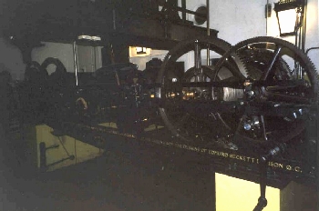
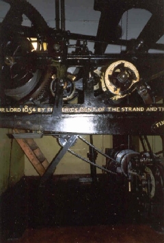
The three trains are mounted in a cast iron frame which is almost 15 feet long and spans two pedestals on either side of the clockshaft. Along the base of the front and back of the frame is a long inscription which reads: 'THIS CLOCK WAS MADE IN THE YEAR OF OUR LORD 1854 BY FREDERICK DENT OF THE STRAND AND THE ROYAL EXCHANGE, CLOCKMAKER TO THE QUEEN, FROM THE DESIGNS OF EDMUND BECKETT DENISON Q.C.' (Edward John Dent died in 1853). [A drawing of the movement by Denison in his book A Rudimentary Treatise on Clocks, Watches and Bells renders the inscription incorrectly; Denison omits 'the' before 'Royal Exchange' and has 'design' instead of 'designs'. A more serious error in this drawing, however, is Denison's association of the wrong countwheels with the striking and chiming trains. Were he still alive, we would love to see his reaction.] A small plate below this reads "FIXED HERE 1859". Although completed in 1854, delays in completing the tower and bells meant it could not be installed until 1859.
We will now describe each train in turn.
The going train
We are not going to give a complete description of how a clock works. If you are not familiar with the basic principles of operation of a pendulum clock, more information may be obtained from some of the sites on our links page. For those who are familiar, it will suffice to say that the going train provides direct drive to the hands and Denison's double three-legged gravity escapement. There is no remontoire and maintaining power is provided for while the clock is being wound. The arbors of this train are shorter than those of the chiming and striking trains and do not span the breadth of the clock's frame. Famously, the adjustments to compensate for variations in the clock's rate are made by placing pennies on a convenient ledge on the pendulum behind the clock, thus altering the position of its centre of gravity. Drive to the hands is by an oblique shaft which drives bevel gears positioned centrally on a gantry above the clock, with four shafts running out to each dial. Because there is no remontoire the hands on the dials advance by 2 seconds every two seconds, i.e. at every swing of the pendulum.
Click here to view a larger image and explanation
Image courtesy of Kimberly Ennico
The chiming train
The chiming train occupies the space on the right hand side of the clock. The largest driving weight, 1.25 tons, is used to power this train. A series of cams at the rear of the very large winding barrel rotate with the barrel and operate five levers which pull and release the five cables attached to the five hammers of the four quarter chiming bells. The reason why one bell has two hammers will be seen on reference to the scheme for the Westminster Chimes, where the F natural bell must sound twice in quick succession. This quick repetition would not allow sufficient time for a single hammer to operate twice. The speed of the striking is controlled by the rotation of the large fly fan which is located high above the clock close to the ceiling. The fly is driven by a long vertical arbor, and it was the failure of this arbor which caused the disaster in 1976. The chiming sequence is controlled by a countwheel. This is a wheel with notches cut in it which rotates slowly as the winding barrel turns. The notches are carefully positioned so that at the correct stage of the chiming sequence a lever drops into a notch and stops the chiming. The next part of the sequence is played when the chiming train is next released by the going train.
Some of these points may be seen on reference to the following picture.
Click here to view an explanation
Image courtesy of AEA Technology
The striking train
The striking train, located on the left hand side of the frame, is essentially similar to the chiming train and we may simply point out some of the differences. This train is driven by a somewhat lighter weight, which is still very substantial at 1 ton. There is a single series of very large cams at the rear of the winding barrel which raise and release a lever which operates the hammer of the Big Ben bell. Once again the rate of striking is controlled by a large fly fan near the ceiling and the number of strokes is controlled by a similar countwheel. This train is triggered by the going train and Denison designed the movement carefully to ensure accuracy in the timing of the first stroke. The chiming train always starts chiming the hour about twenty seconds before to allow the chimes to complete before the striking of Big Ben.
The following picture illustrates parts of the striking train and going train.
Click here to view a larger image and explanation
Image courtesy of AEA Technology